How line drawing works
This page explains the public jett::lines() API and the internal model that turns line segments into filled geometry.
The drawing model
The line API accepts a sequence of points, a width, a colour, and a small set of flags that control how the stroke should be rendered.
Internally the library does not keep the line as a mathematical centre line all the way to the final write. Instead it works like this:
- each line segment becomes a widened polygon,
- neighbouring polygons are connected at their shared corner,
- the final geometry is filled by the polygon rasteriser.
That design means thick lines and polygons share the same rasterisation rules, and anti-aliased lines reuse the anti-aliased polygon filler.
A basic line draw
#include "GraphicsLibrary/jett.h"

int main(int argc, const char* argv[])
{
	jett r;
	r.init(false);

	jett_image image;
	image.createImage(250, 250, image_cmyk);
	image.erase();

	jett_point points[2];
	points[0] = jett_point(10, 10);
	points[1] = jett_point(240, 240);

	unsigned char cmyk_col[4] = {0, 255, 0, 0};
	r.lines(image, cmyk_col, 4, points, 2, false, 0);

	image.saveToFile(_T("output.tiff"));
}
Width and point order
The width parameter is the full visual width in pixels. Internally the stroke builder offsets geometry on both sides of the segment centre line.
Point order matters for multi-segment paths because the library uses that sequence to determine which corners should receive join treatment.
Line joins
The join style controls what happens where two widened segments meet.
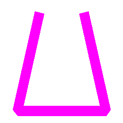
line_join_none
Each segment is painted as its own widened shape. The wedge at the corner is not filled in.
Use this when you want each segment to remain visually independent or when you want to avoid any corner extension at all.
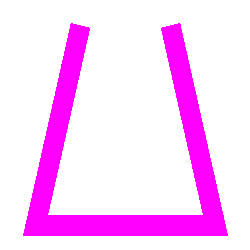
line_join_bevel
This is the most practical general-purpose join. The outside corner is cut off with a straight edge, producing a flattened corner.
Bevel joins stay stable even when the angle is sharp, which is why they are a good default for print-oriented overlays and UI-like shapes.
line_join_miter
The outside edges of the two segments are extended until they meet. This preserves a sharp corner and best follows the apparent direction of the stroke.
Miters are visually strong, but they can become very long at acute angles. The implementation therefore falls back to a bevel join when the intersection is unstable or would extend too far.
Open versus closed paths
If the close parameter is false, the stroke is treated as an open polyline and the first and last segments end as flat geometric caps.
If close is true, the last point is joined back to the first point and the same join rules are applied at the closing corner.
Anti-aliasing
line_fast chooses speed. Pixels are either in or out.
line_best uses the anti-aliased polygon path to compute smoother edge coverage. This costs more, but it is the better choice when the linework will be inspected on screen or contains diagonals and small details.

line_best is most noticeable on diagonals and sharp corners, where the stroke edge no longer steps harshly from pixel to pixel.Choosing the right style
- Use
line_fastfor crop marks, barcode frames, masks, and other hard-edged technical graphics. - Use
line_bestfor logos, overlays, or UI-like marks that benefit from smoother edges. - Use
line_join_bevelwhen you want predictable corners. - Use
line_join_miterwhen the stroke direction matters and the corners are not extremely acute. - Use
line_join_nonewhen segments should read as separate pieces.
Multi-segment example
#include "GraphicsLibrary/jett.h"

int main(int argc, const char* argv[])
{
	jett r;
	r.init(false);

	jett_image image;
	image.createImage(250, 250, image_cmyk);
	image.erase();

	jett_point points[4];
	points[0] = jett_point(25, 25);
	points[1] = jett_point(25, 225);
	points[2] = jett_point(225, 225);
	points[3] = jett_point(225, 25);

	unsigned char cmyk_col[4] = {0, 255, 0, 0};
	r.lines(image, cmyk_col, 20, points, 4, false, line_join_bevel);

	image.saveToFile(_T("output.tiff"));
}