Hardware & Audio Design
What this component needs from the processor, the audio codec hardware, the echo-cancellation reference, and the microphones — and why AEC is not a substitute for good physical audio design.
Supported processors
aec_speexdsp is plain C compiled from the vendored, BSD-licensed SpeexDSP
sources. The complete component also requires an ESP-IDF peripheral with TDM
support; an FPU alone is insufficient. ESP32-S3 and ESP32-P4 have both TDM
and hardware floating-point support. The original ESP32 and ESP32-S2 lack the
required TDM mode and cannot use this transport. See Espressif’s
I2S mode support table.
Other TDM-capable targets still need CPU, memory and board validation. Long
filters (up to ~1 s of echo tail) can cover longer acoustic paths, but do not
guarantee better cancellation when a shorter filter already covers the path.
The component is known to work on the ESP32-P4 in the Waveshare ESP32-P4-WIFI6-Touch-LCD-7B, the reference/test board for the configuration in this repository. Other variants use the same component API but should be treated as ports that still need board-specific I2S, memory, codec, and acoustic validation unless that board has also been tested.
The component requires:
- ESP-IDF, not the Arduino framework;
- enabled, working PSRAM for the microphone handoff buffers;
- enough CPU headroom for two real-time FreeRTOS tasks and the selected processing stages.
ESP32-P4 has no integrated Wi-Fi, so a networked ESPHome device also needs a supported companion radio arrangement, such as an ESP32-C6 using ESP-Hosted. That radio is unrelated to the audio pipeline.
Audio hardware
Look for a board or design with:
- a two-or-more-channel audio ADC/codec capable of 16-bit, 16 kHz, four-slot I2S/TDM output;
- two microphone signals in distinct TDM receive slots;
- a DAC/codec capable of receiving 16-bit, 16 kHz TDM audio;
- an amplifier and loudspeaker;
- shared MCLK, BCLK and LRCLK, plus one data input and one data output;
- either an analog playback/reference signal captured in a third ADC slot, or
use of the component’s digital
playbackreference; - five suitable GPIOs for MCLK, BCLK, LRCLK, DIN and DOUT, plus any I2C/control and amplifier-enable pins required by the codecs.
This implementation specifically requires four-slot I2S/TDM, not ordinary
two-channel I2S. At every 16 kHz frame boundary, the bus carries four 16-bit
time slots on a shared data wire. On receive, two slots contain microphones and
another can contain the hardware reference; the remaining slot may be unused.
On transmit, tx_slots selects the two slots consumed by the DAC. MCLK, BCLK,
and LRCLK are shared between RX and TX so capture, reference, and playback stay
synchronized. The component configures Philips-format TDM as the master and
drives all four slots. Before buying a board or codec, verify in its datasheet
and schematic that it can operate in this mode and that its slot positions are
configurable or documented.
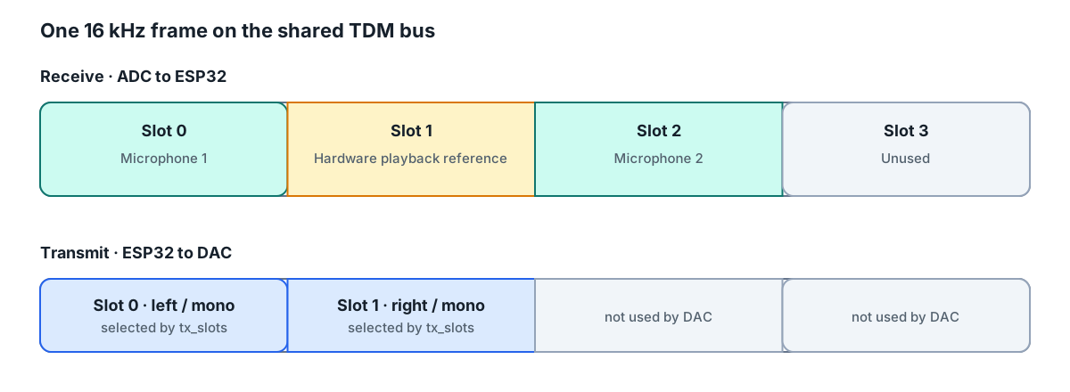
This is the verified Waveshare 7B mapping. Other boards can place the same signals in different slots.
Do not choose hardware based only on a feature list saying “dual microphone” or “AEC.” Check the schematic and codec documentation for all of the following:
- both microphones are routed to separate ADC channels and separate TDM slots;
- the ADC can output four 16-bit slots at 16 kHz;
- the DAC can consume the same clocking and TDM frame while RX is active;
- a genuine playback-derived hardware reference is routed into an ADC channel;
- the reference slot, microphone slots, and DAC TX slots can be identified;
- the ESP processor exposes the required I2S/TDM peripheral and GPIO routing;
- PSRAM is fitted and enabled;
- the amplifier and speaker can produce clean speech without clipping or severe enclosure vibration.
The original implementation uses an ES7210 microphone ADC and ES8311 DAC, but
the component is configured by ESPHome audio_adc, pins, and slot numbers and
is not intrinsically tied to those parts. The ADC and DAC must share the bus
format expected here. This component is the I2S master and always configures
four active, 16-bit Philips-format TDM slots at 16 kHz.
Board manufacturers, including Waveshare, sometimes describe the ES7210 as an
“AEC chip” or “echo cancellation chip.” That description is misleading. The
ES7210 is a multi-channel audio ADC: it digitizes the microphones and can
digitize a hardware reference routed to one of its inputs, but it does not run
the adaptive echo-cancellation algorithm used here. Actual AEC, nonlinear
processing, noise suppression, and AGC run on the ESP32 itself, in the
SpeexDSP-based aec_speexdsp component. An
ES7210 is useful AEC-supporting hardware only when the board routes the
necessary microphone and reference signals to it.
The reference hardware is the Waveshare ESP32-P4-WIFI6-Touch-LCD-7B. It combines an ESP32-P4 with PSRAM, two onboard microphones, an ES7210 capture ADC, an ES8311 playback codec, a speaker connection, and an ESP32-C6 companion for networking. The tested pin and slot mapping is shown in the installation guide. Similar-looking Waveshare models should not be assumed to use the same audio routing without checking their schematics.
For best results, place the two microphones consistently, avoid mechanical coupling from the loudspeaker, prevent analog clipping, and provide a clean reference. An analog reference should represent the real playback chain as closely as possible. A digital reference is easier to wire but does not include DAC/amplifier delay, gain, nonlinear distortion, or speaker coloration.
Reference audio
AEC needs to know what sound the device intended to play. That known signal is called the reference or far-end reference. The echo canceller compares it with the microphone signals to find the part of the recording caused by the device’s own speaker. Without a strong, correctly timed reference, the canceller cannot distinguish speaker echo from the user’s voice and cancellation will be poor.
The component requires a synchronized hardware reference. AEC is very sensitive to timing alignment between the reference and the microphones. It will only work effectively with a hardware reference captured in sync with the microphone channels.
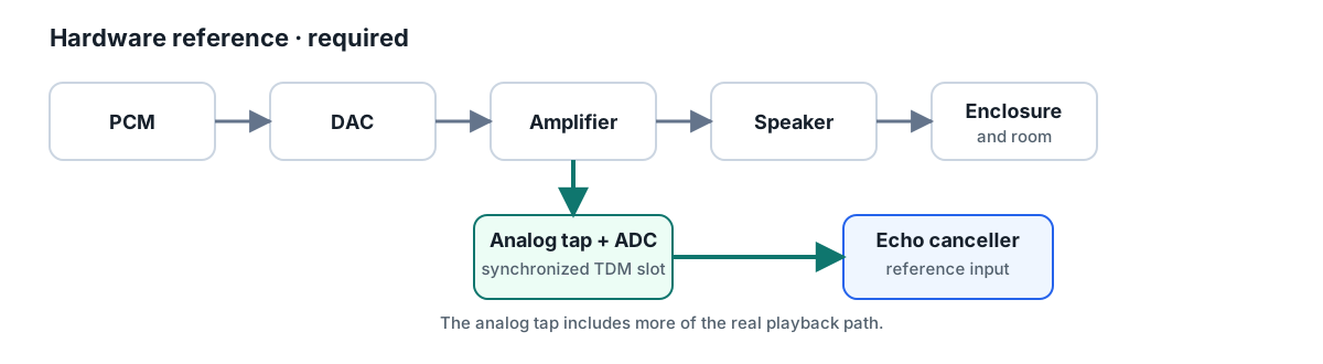
Hardware or analog reference (analog_slot)
A board designed for AEC may route the DAC, amplifier input, or another point in
the speaker path back into one channel of its ADC. That channel arrives as a TDM
slot beside the microphones. Configure that slot as reference_slot.
A well-designed hardware reference is required. It stays in the same hardware clock domain as the microphones and can include real playback-path delay and gain. Depending on where the board samples it, it may also include DAC or analog-chain effects. It still does not perfectly describe the acoustic speaker output, so gain, polarity, routing, and clipping must be checked.
When choosing hardware, inspect the schematic rather than relying only on an “AEC” product label. Look for a signal from the speaker/DAC path routed back to an ADC input, and confirm which TDM slot carries it. A spare ADC channel that is not actually connected to playback is not a reference.
Microphones
The component accepts one to four microphone slots. Without beamforming,
first or second processes only that selected microphone. With beamforming,
all configured microphones are
echo-cancelled in one multichannel state and combined before a shared
preprocessor. Two microphones give the device spatial
information: a nearby speaker, a person in front of the panel, and background
noise reach the two capsules at different levels and times. The beamformer
uses those inter-microphone time differences to steer toward the speaker.
The microphones should be the same type, use comparable analogue paths and gain, and remain synchronized on the same ADC/TDM clock. Give them meaningful physical separation; two capsules at effectively the same point provide little spatial information. As a practical starting point, use several centimetres of separation and follow Espressif’s microphone-array guidance or the layout of a known-good voice board. More distance is not automatically better: excessive spacing, asymmetric enclosure ports, or one microphone much closer to the loudspeaker can make the two channels inconsistent. Preserve a clear acoustic opening for each microphone and avoid placing either in the speaker’s immediate pressure field.
Compared with publishing either raw microphone directly, echo cancellation with two channels can:
- use both channels to favour speech with the better signal-to-noise ratio;
- suppress some spatial interference and steady background noise;
- apply echo cancellation to each synchronized microphone observation;
- produce a single enhanced channel, simplifying wake-word and speech-to-text consumers;
- normalize the final level with AGC, improving recognition of users speaking at different distances.
Those advantages depend on correct slot mapping and matched, unclipped inputs. If one channel is silent, swapped with the reference, badly clipped, reversed, or has very different gain, dual-microphone processing may perform worse than a clean raw microphone. Test every physical slot before enabling the complete pipeline.
Physical audio quality still matters
AEC is not a substitute for competent acoustic and electrical design. Cheap or overdriven speakers often distort, producing harmonics that are absent from the reference and therefore difficult to cancel. Buzzing enclosures and poor amplifiers cause the same problem. Keep playback below the point of audible or measured distortion.
Do not place the loudspeaker immediately beside or mechanically coupled to the microphones. Provide useful distance, orient the speaker away from them where possible, isolate vibration, avoid enclosure resonances, and prevent the ADC inputs from clipping. A clean hardware reference and clean playback path usually improve AEC more than increasingly aggressive software settings.