First-Time Board Setup and AEC Bring-Up
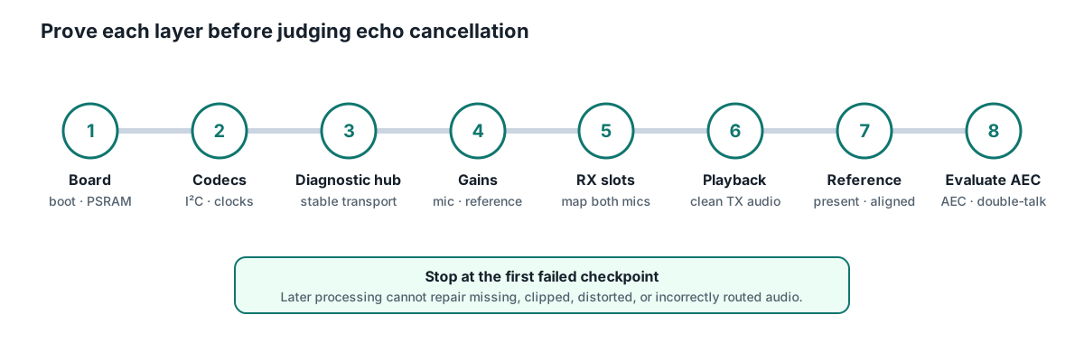
Porting the component to a new board is primarily a hardware-validation exercise. Display, networking, codec control, raw capture, playback, input gains, and the AEC reference are separate systems; prove each one before evaluating echo cancellation.
The Waveshare ESP32-P4-WIFI6-Touch-LCD-7B settings in the installation guide are the tested reference. Do not copy its GPIOs or TDM slots to a similar-looking board without checking that board’s exact revision and schematic.
If you have the Waveshare 7B itself, use the ready-made audio-test example for the steps below. Its touch UI exposes all four raw slots, levels, spectrum, recording, and test playback without requiring a rebuild for every diagnostic selection.
Before you start
Collect the schematic and datasheets for the processor, microphone ADC, playback DAC/codec, and amplifier. Record:
- ESP32 target, flash size, and PSRAM type and size;
- I2C pins, codec addresses, and power rails;
- MCLK, BCLK, LRCLK, DIN, and DOUT pins;
- amplifier enable, mute, reset, and their active levels;
- ADC input routing and four-slot TDM order; and
- the two TDM slots consumed by the DAC.
The components require ESP-IDF, four-slot, 16-bit, 16 kHz TDM, and synchronized microphone channels. Use a TDM-capable target, preferably with a hardware FPU (ESP32-S3 or ESP32-P4), and working PSRAM for the microphone buffers. A hardware playback reference is required. See Hardware & Audio Design before selecting or wiring a board.
1. Prove the board without audio
Start with a minimal ESPHome configuration. Confirm that the processor boots reliably, PSRAM is detected, logs are stable, and API/OTA networking works. If the device also has a display or touch panel, prove those separately before adding the codecs or the audio hub.
Save this minimal configuration as a recovery image. It gives you a known-good baseline if later audio work causes memory pressure or boot failures.
2. Initialize the codecs
Add the I2C bus and the ADC/DAC control components, but keep the rest of the configuration simple. Enable I2C scanning during bring-up and confirm both devices acknowledge at their expected addresses.
Configure 16-bit samples at 16 kHz. The ADC must output four-slot TDM and the DAC must accept the same clocks and framing. If using the ES7210, follow the extra TDM-component note in the installation guide. Correct digital clocks can still produce silence if a codec rail, mute line, or amplifier enable is wrong, so verify those signals against the schematic.
3. Add the audio hub in diagnostic mode
Copy the hub, microphone, and speaker structure from the installation guide, then replace the board-specific pins. Begin with the conservative diagnostic baseline:
aec_speexdsp:
  # audio_adc and the five I2S/TDM pins go here
  tdm_slots: 4
  frame_size: 256
  filter_length: 1024
  diagnostic_raw_slot: 0
  slot_logs: true
  diagnostics: true
Do not configure another component to own the same I2S peripheral or GPIOs. Flash over USB and inspect the startup log. Resolve allocation, I2S, or codec errors before assessing audio quality.
4. Set microphone and reference gains
Correct input gains are a bring-up gate, not a later tuning detail. The AEC, AGC, and every subsequent check assume clean, unclipped microphone and reference signals; no DSP setting can repair samples that were already clipped by the ADC.
With the hub still in diagnostic mode (slot_logs: true or the audio-test
meters), play a repeatable test signal through the component’s speaker at the
loudest intended volume and set both levels:
- Microphones. Speak at the normal usage distance and adjust the ADC gain
(
mic_gainon the ES7210) until speech is strong but peaks stay well below digital full scale. Both microphone slots should end up similarly sensitive. Leave headroom: AEC and AGC cannot recover clipped samples. - Reference. The analog reference must closely follow playback without
reaching digital full scale. Lower that slot’s ADC gain first; if the
reference level is still too high at the minimum gain, reduce the DAC output
with the software DAC output gain
playback_gain_db(the Waveshare 7B uses-12dB). It attenuates audio before it reaches both the DAC and the reference tap, trading a little maximum playback volume for an undistorted reference. Re-test the speaker and the raw reference at the loudest intended volume afterwards. See Prevent reference clipping.
5. Map every receive slot
Set diagnostic_raw_slot to each value from 0 through 3, rebuilding as
needed. Listen to or record the published microphone while you:
- speak or rub a finger near each microphone in turn;
- play a repeatable test signal through the speaker; and
- observe the raw-slot RMS/peak logs.
Both microphone channels must be intelligible, similarly sensitive, and free of clipping, buzz, repeated samples, and incorrect pitch. If the levels are wrong, return to the gain check in step 4 before continuing.
Update microphone_slots only after this test. On the reference Waveshare 7B,
the tested microphone slots are [0, 2] and slot 1 is the hardware reference;
another board may differ.
6. Verify playback
Send signed 16-bit, 16 kHz mono or stereo PCM through the component’s speaker.
Check that playback reaches the intended DAC channels cleanly and that capture
continues during playback. If there is silence or distortion, verify DOUT,
tx_slots, codec volume/mute, amplifier control, speaker wiring, and TDM framing.
resampler: true compensates for small sustained rate differences. It is not a
decoder or a general sample-rate converter, so source audio must still be
nominally 16 kHz PCM.
7. Verify the reference
For reference_source: analog_slot, test the proposed slot in diagnostic mode.
Its level was set in step 4; re-check it here if playback sounds distorted.
It should be quiet when playback is stopped, closely follow playback when it is
active, and respond little to room speech. A spare or microphone-connected ADC
channel is not a playback reference. Set the verified slot as reference_slot
and use the captured reference directly.
AEC is very sensitive to timing alignment between the reference and the microphones. It will only work effectively with a hardware reference captured in sync with the microphone channels.
8. Enable and evaluate the DSP
Remove diagnostic_raw_slot to publish the cleaned output. Test the same
phrase in three conditions: speech only, playback only, and simultaneous speech
and playback. A successful configuration substantially reduces playback while
keeping near-end speech intelligible; complete silence is not a realistic goal.
Tune in this order:
- correct slot mapping, clean levels, and stable TDM transport;
- correct hardware reference alignment and level;
noise_suppression_level_db, thenecho_suppress_db/echo_suppress_active_db;filter_length— a plain sample count (see choosing an echo filter length); and- optional noise suppression, AGC, meters, and resampling.
Change one setting per test. Test several playback volumes and reject a setting that suppresses the user’s voice during double-talk, even if its playback-only result sounds quieter. See Testing & Tuning for the repeatable test procedure.
Filter length is also a CPU-budget decision. Start at the 2048-sample
default and raise it only while the DSP load log stays comfortably below
100%. A firmware image booting successfully does not prove that it can process
and deliver audio continuously.
Troubleshooting the bring-up
- DSP load near 100% or PSRAM state: enable the performance
sdkconfig_options, then reducefilter_lengthuntil the load log and memory placement are comfortable. - All slots are silent: verify codec power, MCLK/BCLK/LRCLK, DIN direction, and four-slot TDM mode.
- One microphone is missing: scan all four slots, then check bias, routing, soldering, and per-channel gain.
- Crackles or wrong pitch: recheck 16-bit framing, the 16 kHz clock, shared clock wiring, and diagnostics counters.
- Reference behaves like a microphone: the proposed ADC input is not a real playback feedback path; inspect the schematic.
- AEC fails only at high volume: the speaker, amplifier, reference input, or
microphone ADC is probably clipping or nonlinear. Set
playback_gain_dbto retain digital headroom (the Waveshare example uses-12), lower analogue gain if possible, or improve the physical audio path. Once a sample is clipped, AEC and AGC cannot recover it.
Keep the final board revision, codec addresses, pins, verified RX/TX slots, gains, maximum clean playback volume, ESPHome version, and DSP settings with the working configuration. Those details make a port reproducible and upgrades testable.
After these checks pass on a Waveshare 7B, the complete voice-assistant example is the recommended next step.